Where does the recycled carbon fibre actually come from?
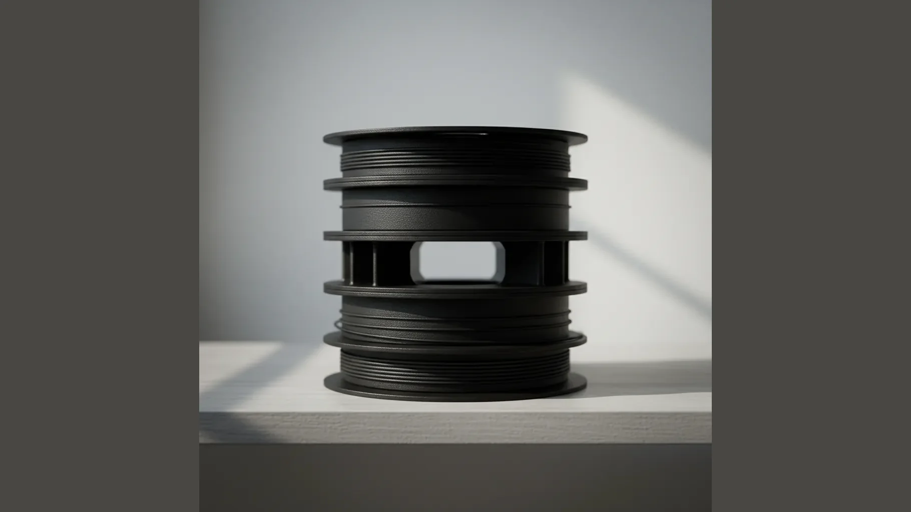
The 8% rCF content is post-industrial scrap, sourced from two main streams. The first is manufacturer cutting waste: when carbon-fibre prepreg is laid up for aerospace, automotive, or sporting-goods parts, the offcuts are non-load-bearing scrap that historically went to landfill or incineration. UK and EU CF prepreg producers now sell this stream to recyclers who mill it into chopped fibre for engineering compounds. The second is decommissioned wind-turbine blade reclaim · a growing waste stream as the first generation of UK and European wind turbines reach end-of-life. Blade composites are pyrolysed or mechanically processed to recover the carbon fibre.
The recycled chopped fibre is roughly 100-500 microns long after processing · long enough to deliver meaningful mechanical reinforcement in the PETG matrix but short enough to spool through standard 1.75 mm filament without aggregation. The 8% by mass loading is a deliberate sweet spot: enough to deliver the +18% tensile and +75% stiffness gain seen on this page, while staying below the loading where filament becomes too brittle to spool reliably. For ESG-procurement-aware briefs, the rCF mass-fraction declaration is available on request and supports Scope 3 reporting (recycled vs virgin material accounting) plus circular-economy compliance.
How does 8% chopped CF lift the mechanicals so much?
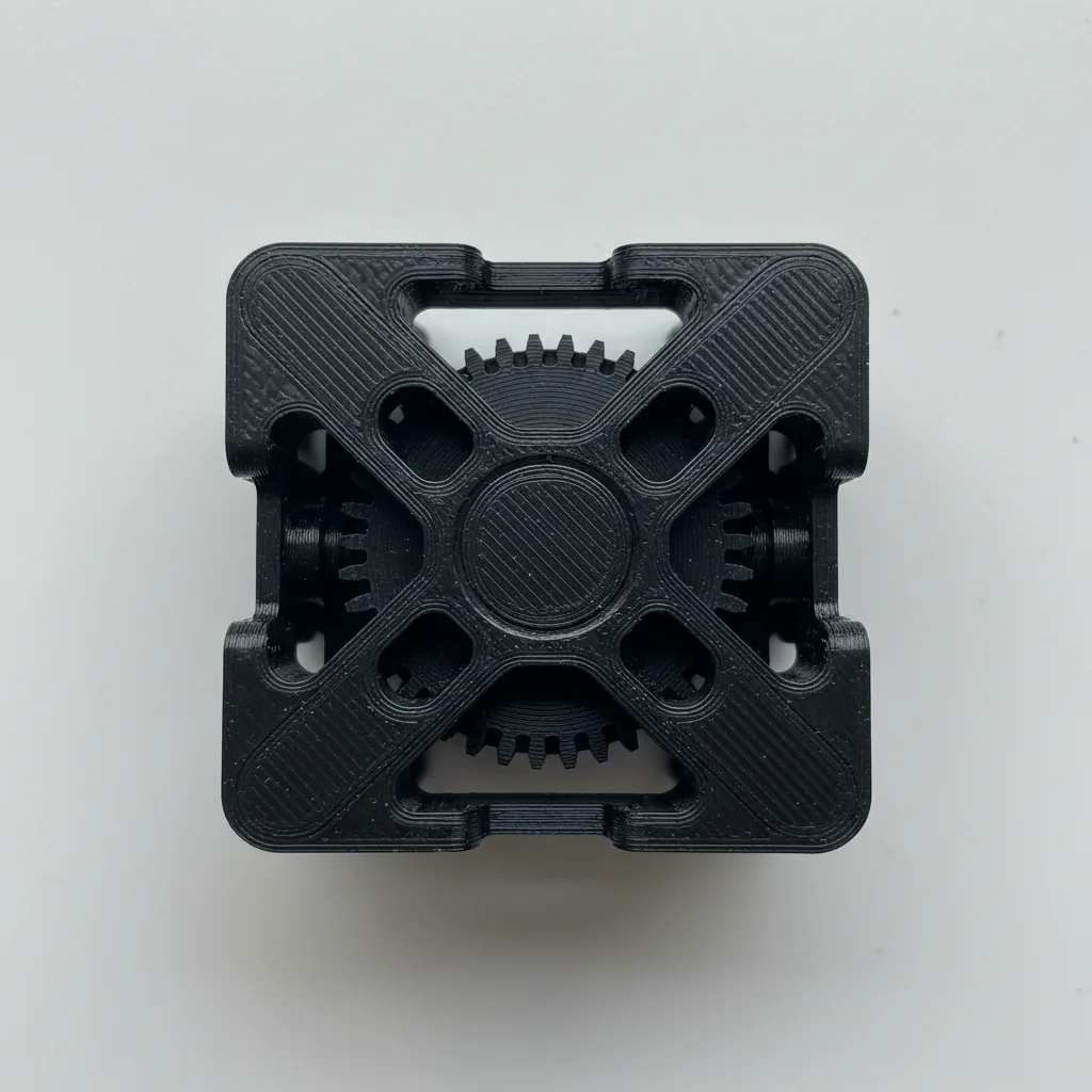
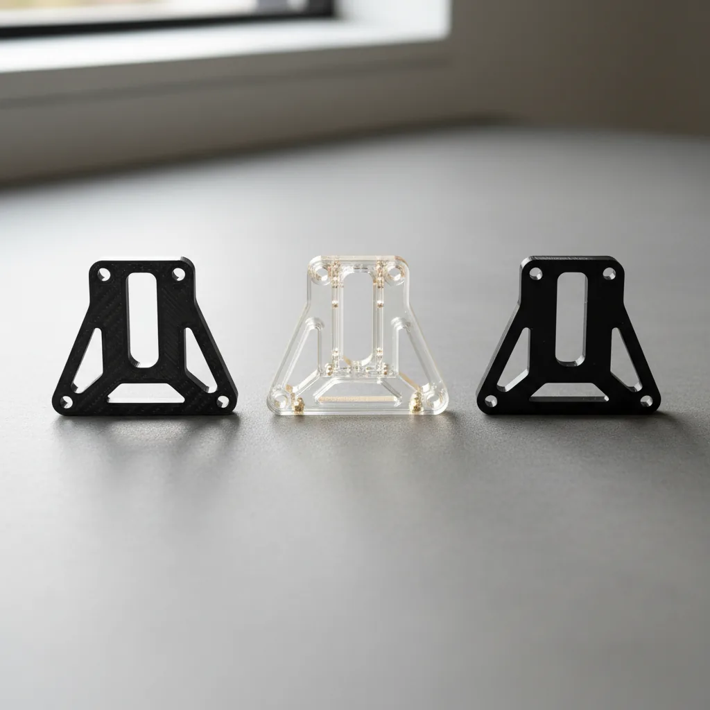
Three mechanisms. First, the chopped fibres are an order of magnitude stiffer than the polymer matrix (~230 GPa modulus for CF vs ~2 GPa for plain PETG) · stress applied to the part is preferentially transferred to the fibres, raising the bulk Young's modulus along the load path. Second, the FDM extrusion process aligns the chopped fibres along the print path · this means PETG-rCF08 prints with anisotropic reinforcement that favours XY load paths (Z-axis values are correspondingly weaker · 41 MPa tensile Z vs 60 MPa XY). Third, the fibres provide a small toughening contribution by bridging incipient cracks · Charpy notched lifts from 2.6 kJ/m² (plain PETG) to 4.0 kJ/m² (PETG-rCF08).
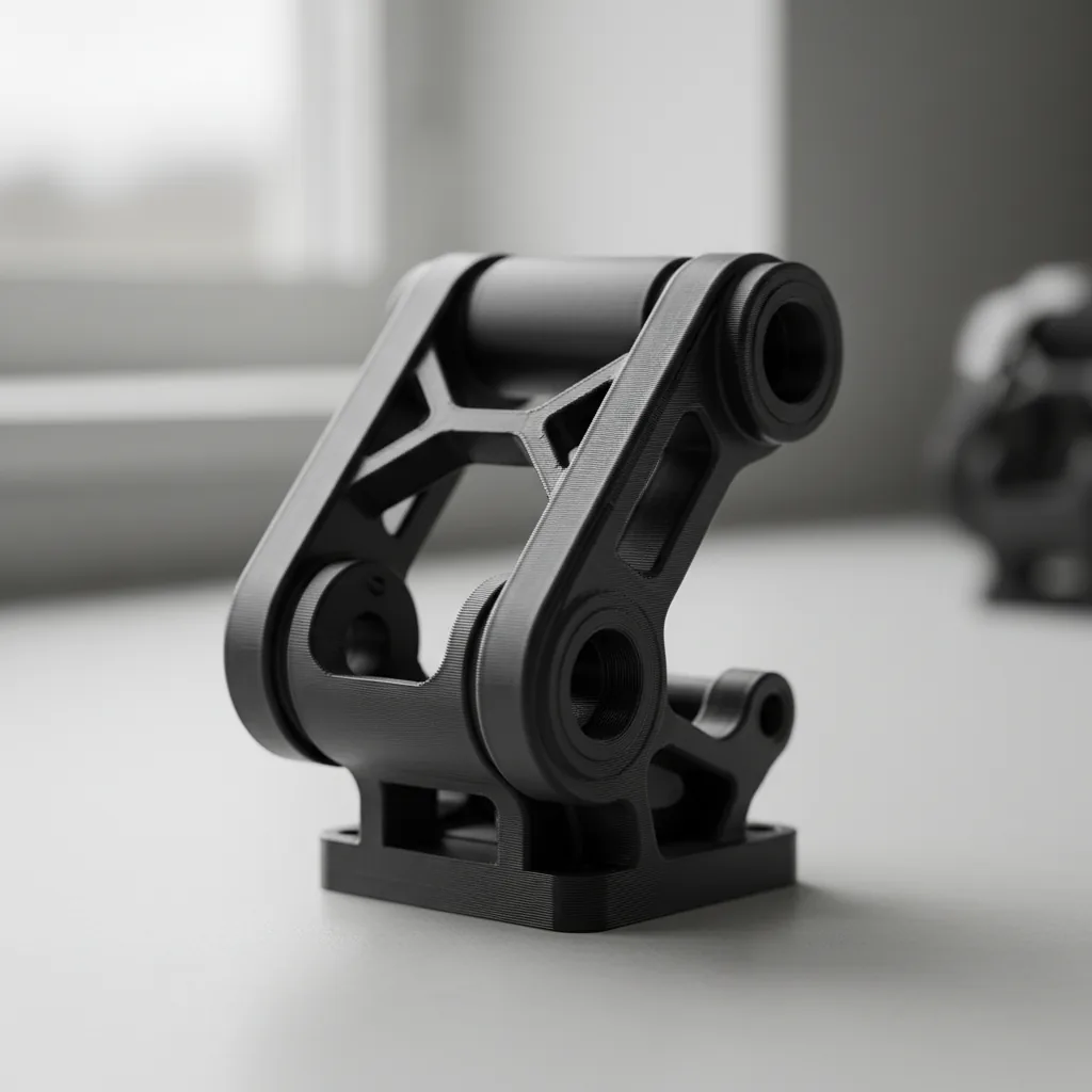
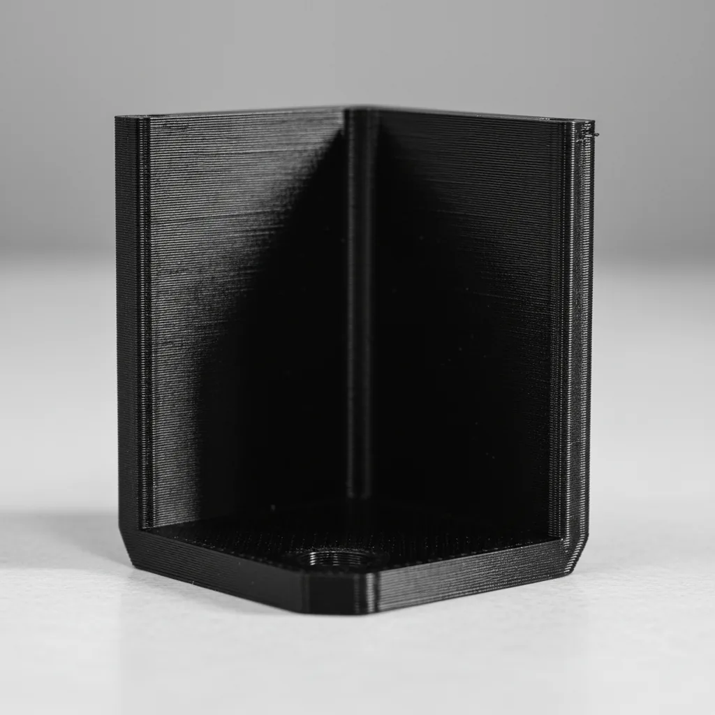
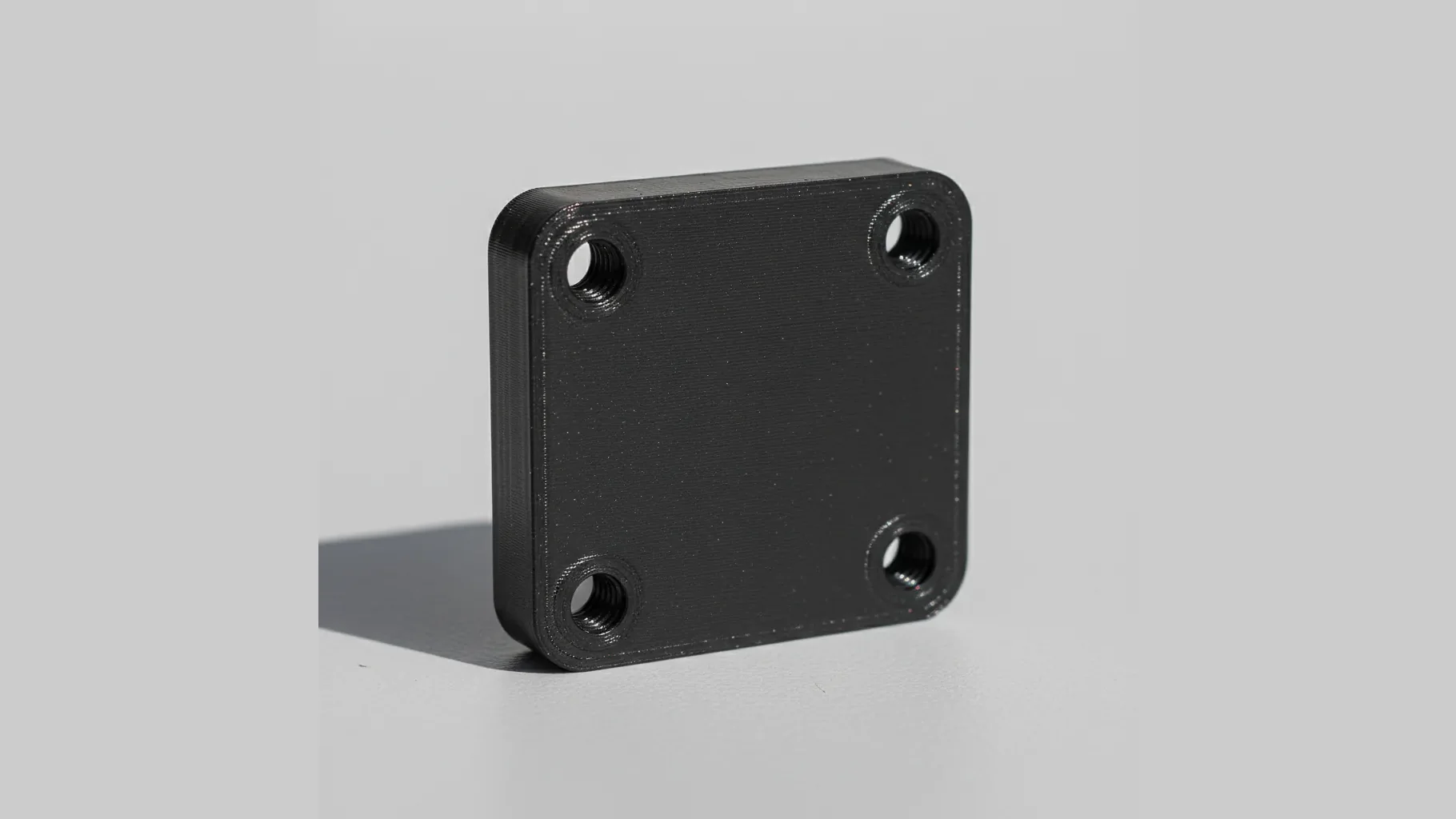
The trade-off is reduced ductility · the rigid fibres limit polymer chain mobility, so elongation at break drops from 8.4% (plain PETG) to 5.7% (PETG-rCF08). Thin features that would bend in plain PETG can crack in rCF08. For design, this means PETG-rCF08 is the right call for stiff bracket geometries with generous wall thickness · less appropriate for snap-fits, living hinges, or anywhere flex matters.
Why does PETG-rCF08 still cap at 65°C service?
The heat ceiling is set by the matrix Tg, not the reinforcement. Carbon fibre itself is stable to 500°C+, but it's the PETG matrix around the fibres that softens · once Tg is passed (69.7°C for PETG-rCF08, DSC 10°C/min) the polymer chains gain mobility, stiffness collapses, and the fibres are now suspended in a soft matrix that creeps under load. HDT at 1.8 MPa is 65.7°C, at 0.45 MPa 68.6°C. Vicat 81.6°C. For sustained service the practical ceiling is ~65°C ambient.
For warmer service the upgrade path is PA12-CF · same CF-reinforcement principle but with a polyamide matrix (Tg ~155°C, HDT 130°C+ class). The cost roughly doubles (PA12-CF £90-130/kg vs PETG-rCF08 £55-80/kg) and the print path requires a heated chamber, but warm-service or sustained-load engineering parts demand it.
Steam autoclave at 121°C is well above HDT · parts deform. For sterilisation, ethylene oxide or IPA wipe-down work for PETG; dry-heat sterilisation below 70°C also works. For repeated steam autoclave service specify PEEK or PPSU. For sustained warm-service parts (engine bay, exhaust-adjacent, oven-adjacent) choose ABS or ASA (HDT 100°C class) or PA12-CF (HDT 130°C+ class).