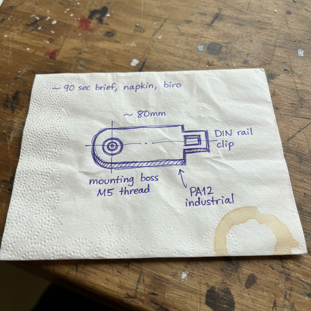
What is CAD design for 3D printing?

CAD design for 3D printing turns a brief — a sketch, a phone photo, a broken part, or an unfinished STEP file — into a manufacturable parametric model. We deliver tolerance-verified STEP files (±0.5mm to ±0.05mm by tier), named-engineer support, and first-article prints in PA12 nylon from 48 hours to 14 days depending on scope.

9,500+ parts shipped from 3D Printing Express this year · UK 3D printing service, Bournemouth

RELIABILITY
0+
parts shipped this year
SPEED
0 hrs
time to receive your part
COMMUNICATION
0h 0 min
average first reply
Year-to-date · 3DPE internal data · updated daily, last verified

Service details and case studies

Telesoft TechnologiesTelesoft Bruff DrinksBruff Drinks DurableDurable BerylBeryl Bikes Bournemouth UniversityBournemouth University Whale TankersWhale Tankers Formula 1F1 HasbroHasbro
£5,000+
Typical cost of a ruined tool

The price of a ruined injection-moulding tool because the CAD wasn't right.

A single wall-thickness mistake, a missed draft angle, an overhang that slumps. Then the tool's already cut. We don't publish an hourly rate, but getting the CAD right the first time is usually a fraction of what getting it wrong costs.

HOW WORK COMES IN

Just send what you've got. We'll translate.

Four ways in, one end deliverable. Start with whatever you already have — a sketch, a drawing, a CAD file, or a part in your hand.

Napkin sketch of a small industrial bracket in blue biro, with handwritten dimensions ~80mm, mounting boss M5 thread, DIN rail clip — on a workshop bench
01 · A hand sketch

Pencil, biro, a quick sketch. Dimensions in mm if you have them.

The fastest path for most jobs. No CAD required. We translate a 90-second sketch into a parametric model and a printed first article.

JPG · PDF · photo of paper

Formal 2D engineering blueprint of the industrial bracket showing the 80mm dimension, M5 threaded mounting boss, DIN-rail slot, title block CAD-BRKT-01
02 · A nice drawing

A 2D plan, side elevation, or a proper blueprint.

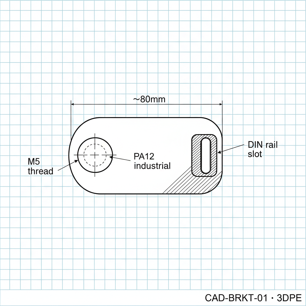
Drawings are gold — they give us the spec without the round-trip. Hand-drawn or CAD-output, both work.

PDF · DXF · DWG

Clean 3D CAD render of the industrial bracket in our parametric CAD style, 3/4 isometric view
03 · We take it into CAD

Then we model it our way — parametric, manufacture-ready.

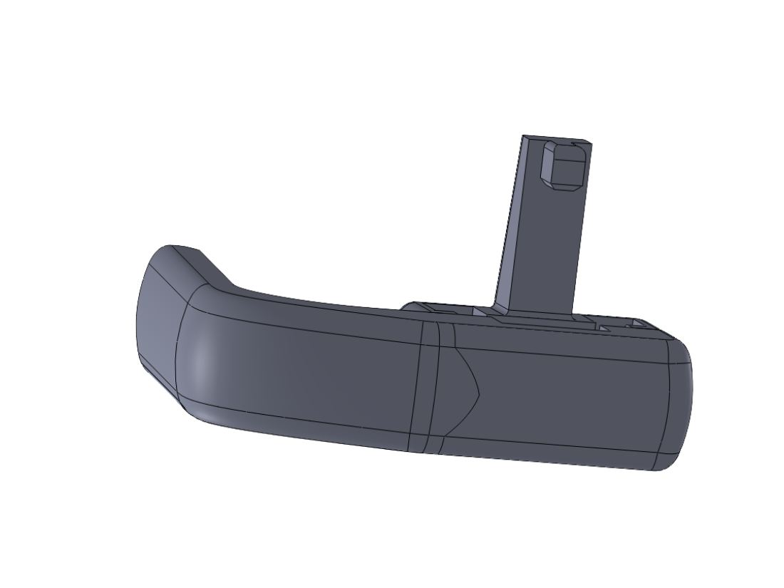
We rebuild your input as a parametric solid in our SolidWorks-compatible workflow. Wall thickness, draft, tolerance ladder — all engineered in before anything prints.

STEP · IGES · STL · 3DM

Photograph of the matte black 3D-printed PA12 prototype bracket on a workshop bench with a steel ruler for scale
04 · The prototype

Then we print it — first article on the workbench.

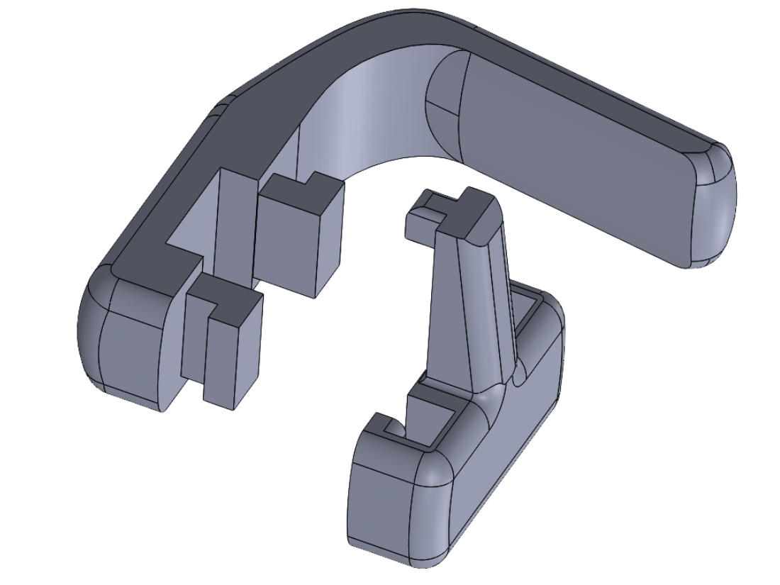
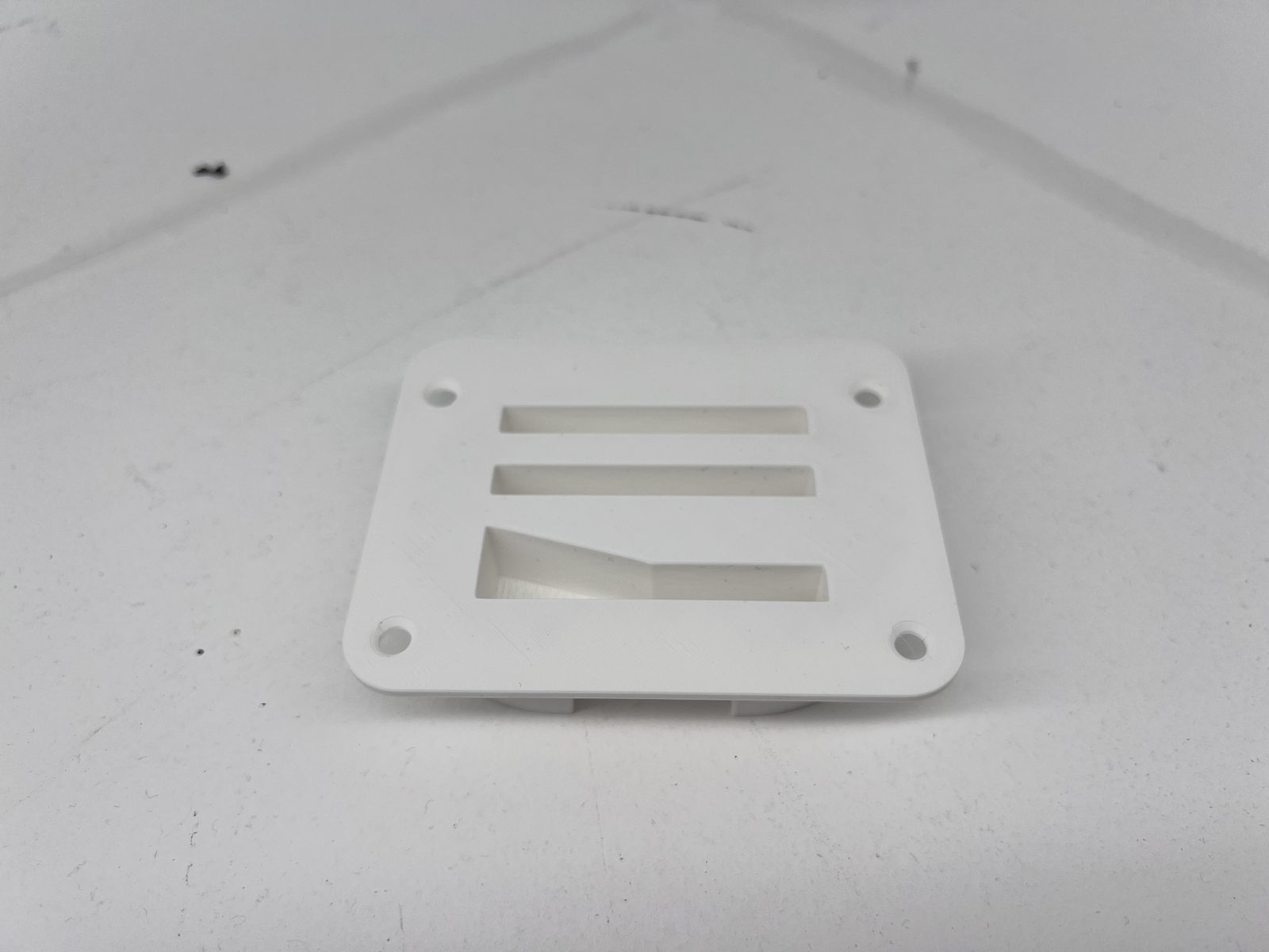
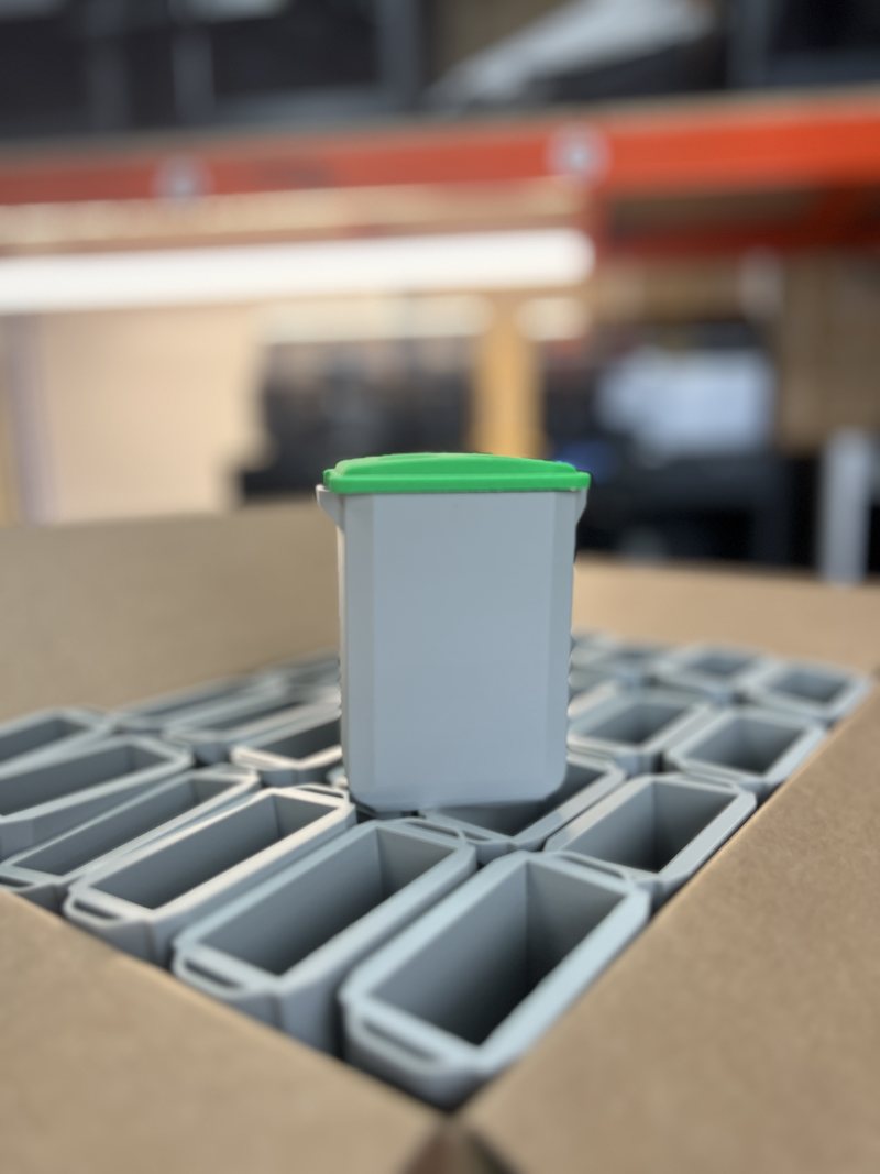
PA12 nylon, ruler in frame, ready for fit-check. The same file goes on to small-batch print if you commit to the run.

First-article print · 48-hour turnaround

Same four moves whether you arrive with a napkin, a photo, or a half-finished STEP file.

From your sketch to a finished part — one path, four sign-off gates, no surprises.

1 · You send sketch · photo · part · CAD 2 · We measure + model parametric · DfAM-ready 3 · DfAM + verify first-article · tolerance check 4 · STEP file (or part) manufacture-ready
No CAD knowledge required at step 1. We translate.

Four steps, each with a tolerance target you can hold us to.

Every step has a sign-off gate. Nothing moves forward without your approval. Tolerance tightens as the design firms up.

  1. 1

    Brief

    15-minute call or a detailed email. We agree scope, deliverable, and fixed working band.

    Target · scope & deliverable agreed
  2. 2

    Concept CAD

    Parametric model in a SolidWorks-compatible workflow, renders + cross-sections for sign-off. Not yet a production file.

    Tolerance · ±0.5mm
  3. 3

    Engineering CAD

    Functional features engineered in. DfAM review · wall thickness, orientation, supports, infill strategy, post-processing.

    Tolerance · ±0.1mm
  4. 4

    Manufacture-ready file

    First-article printed in your chosen material. STEP + IGES out. Editable source on request.

    Tolerance · ±0.05mm

Committed turnarounds, by project shape.

Three tiers, each with a specific window. Timelines count from when the scope is signed off, not from when the brief lands.

Micro-job

48hr
File repair · STL to STEP · single-part tweaks

The "I just need this one thing fixed" tier. Dropped into the schedule around live work.

Standard

3 to 5 days
Single-part CAD · first-article prototype

Most concept-to-functional-prototype jobs land here. Includes one revision round.

Full design

10 to 14 days
Reverse engineering · multi-part · DfAM pass

Full product-design work from sketch / photo / physical to manufacture-ready file.

For the engineer who needs a CAD partner, not an order-taker.

You're running a physical product. Maybe a DTC brand, maybe an early-stage manufacturer, maybe a small engineering team inside a larger business. You know the words tolerance stack, DfAM, first article, draft angle. You've been quoted for injection tooling once and it scared you off. What you don't want is a sales rep to explain 3D printing to you · you want an engineer who'll look at your STEP file, tell you which walls are going to fail in orientation, and show you what to change.

What you get working with us:

  • A named engineer on your project (not an account manager)
  • Parametric models with editable source on request
  • DfAM review with specific recommendations, not generic advice
  • Tolerance ladder published per deliverable tier
  • NDA signed by default, files encrypted, UK-based team
  • Bundled discount if the same job proceeds to print with us
3DPE engineer reviewing a parametric CAD model on screen with a 3D-printed part in hand

Real software, real humans, real tolerance targets.

Most competitor pages say "industry-leading CAD tools" without naming one. We name the stack so you can calibrate whether we're a peer.

CAD stack

Parametric CAD Rhino Fusion 360

We design in SolidWorks-compatible parametric workflows — solid modelling, assemblies, drawings, simulation, PDM. We use Rhino for complex organic surfaces and Fusion for cross-compatibility with client files. Editable source on request.

  • STEP · IGES · STL · DXF out as standard
  • PDM version control on every project over £500 in scope
  • Editable source on request, at project close

Named engineers on your project

James Crisford headshot
James Crisford Product design · DfAM · ICP B liaison
Freddy Blake headshot
Freddy Blake Engineering CAD · tolerance verification · reverse engineering

You get named engineer contact from the Brief call onwards. No account manager, no "a member of our team will be in touch". If James or Freddy can't take your specific job, we'll tell you and point you to someone who can.

Tolerance ladder · published per deliverable

DeliverableToleranceUse
Concept CAD±0.5mmSign-off renders · form factor
Functional prototype±0.1mmFit-check · functional test
Production part±0.05mmFirst-article inspection · scale production
Tighter than ±0.05mmHand-offMedical / aerospace · we refer out honestly

How we compare to other manufacturing processes:

ProcessTypical toleranceBest for
3DPE · FDM±0.2mmPrototypes · low-volume parts
3DPE · SLS / MJF±0.05–0.1mmProduction runs · functional parts
CNC machining±0.025mmTight-tolerance metals · finished surfaces
Injection moulding±0.05mm + £5k+ tool10,000+ unit production runs

Industries we've delivered into

  • Consumer product design · DTC brands, small manufacturers
  • Industrial machinery · obsolete spares, jigs, fixtures, guards
  • Classic cars & automotive · interior trim, non-safety brackets, heritage restoration
  • Agriculture · wear parts, housings, feeder + cage components
  • Domestic appliances · replacement knobs, gears, clips, housings
  • Events & brand activations · one-off prop CAD

We don't claim aerospace or medical certification. If you need AS9100 or ISO 13485 traceability, we'll tell you up front and refer you somewhere that does.
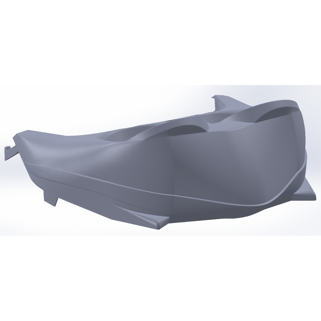
Range of finished 3D-printed engineering parts on workbench 
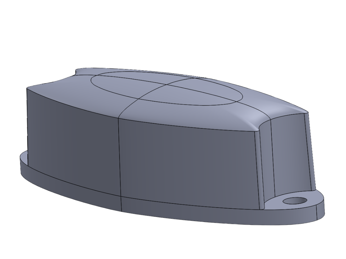
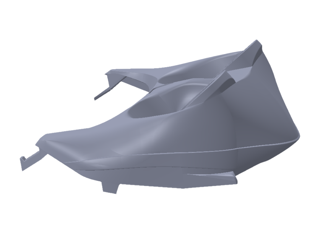
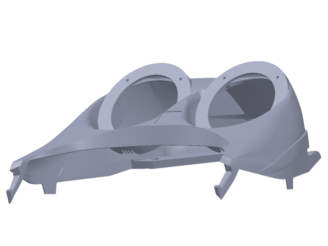
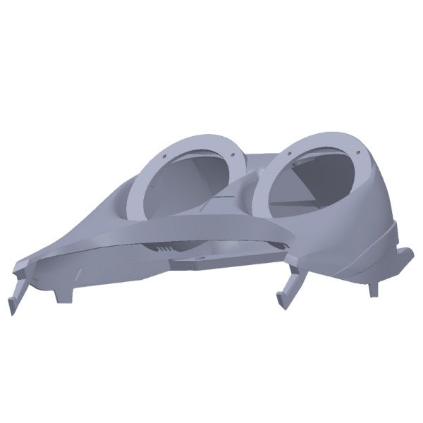
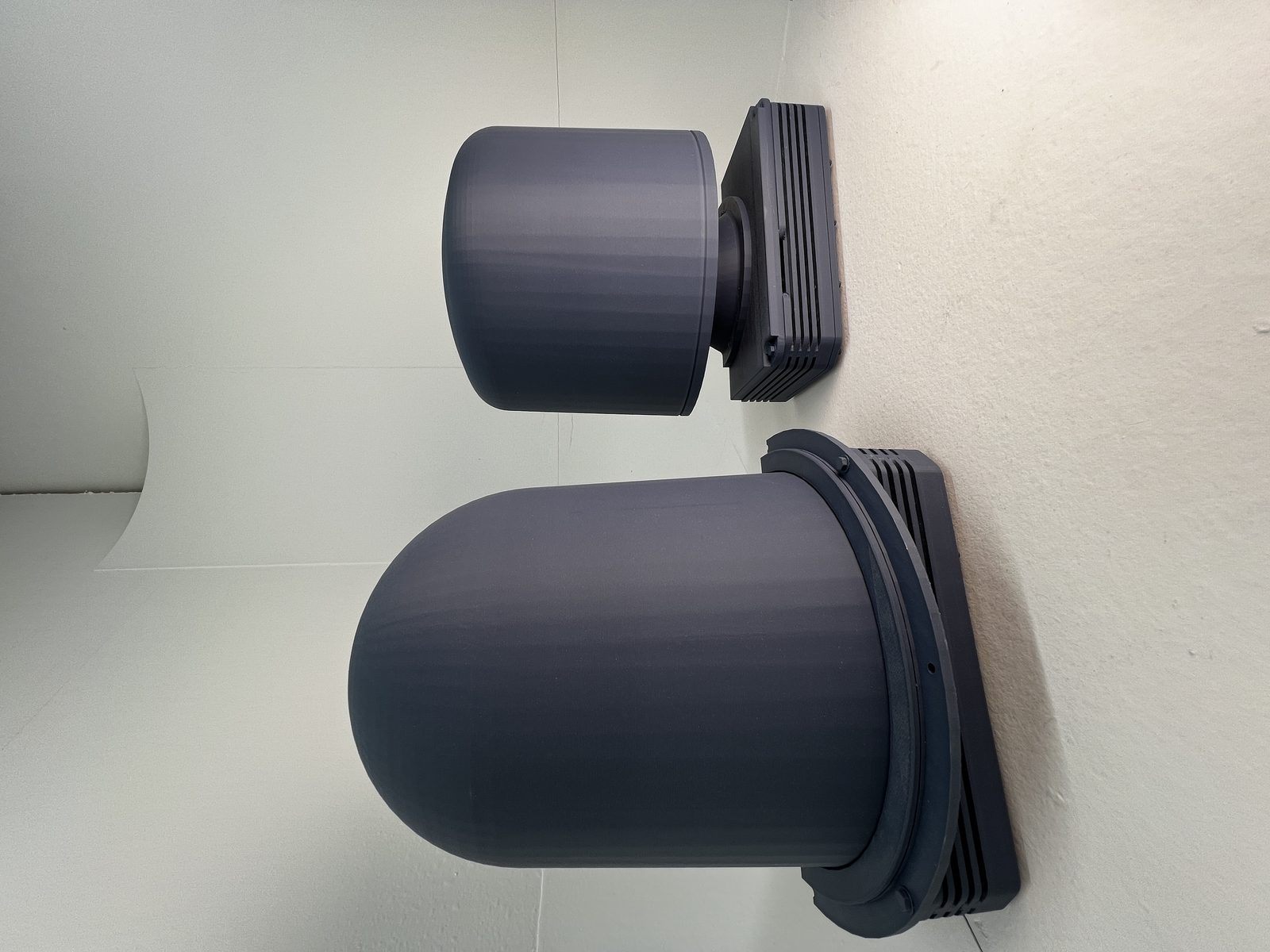
FINISHED PARTS · ENGINEERING-GRADE

Real CAD work, named clients, measurable outcomes.

Load-bearing 3D-printed clip with hand-drawn sketch alongside, showing iteration from concept to production
Product dev · DTC brand

Iterating a load-bearing clip from sketch to scaling at 500 units.

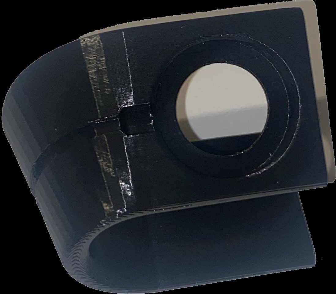
Founder arrived with a hand-drawn bracket concept and a £5k moulding quote that scared them off. We took it through concept CAD, DfAM review, 3 prototype iterations, and into a SLS-printed production run.

Tolerance achieved±0.08mm
Design cycle14 days
First run500 units
Iteration rounds3
Broken OEM machine guard bracket beside its 3D-printed PA12-CF reproduction
Reverse engineering · industrial

Machine guard bracket, no drawings available, idle machine in week three.

Owner posted the broken original. We scanned to point cloud, rebuilt surfaces as parametric solids in a SolidWorks-compatible workflow, printed in PA12-CF. Machine back on line in 8 working days.

Scan accuracy±0.05mm
Reverse eng time6 days
Print + ship2 days
OEM quote was12 weeks
Batch of grey 3D-printed enclosures with green snap-fit lids, packed in a box ready for dispatch
Durable · consumer product

Enclosure design through to a packed, repeatable batch run.

We developed the enclosure in CAD with DfAM for repeatable printing, then produced and packed the batch ready for dispatch.

Run size500 units
Tolerance±0.1mm

What we do

  • Parametric CAD modelling from sketch, photo, physical part, or existing CAD
  • DfAM review on third-party CAD (we don't have to own the model)
  • Reverse engineering from a physical part or an incomplete drawing set
  • First-article prototype + fit-check + iteration included in scope
  • Production-ready STEP files you can hand to any UK manufacturer
  • File repair · STL to STEP · mesh-to-solid conversion · surface reconstruction
  • DfAM optimisation for FDM, SLS, MJF, SLA
  • Editable parametric source (part / assembly files) on request at project close

What we don't do

  • Pure visualisation renders with no manufacturable intent
  • Cosmetic model-kit detail for tabletop wargaming or collector figurines
  • Safety-critical aerospace, medical, or automotive homologation parts
  • AS9100 / ISO 13485 / FDA-traceable material documentation
  • Tolerance tighter than ±0.05mm (we'll refer you to CNC or metrology specialists)
  • Architect-specific scale-model CAD (a future page we may build)
For any of those, we'll tell you within 2 working days and point you somewhere better.
"Do you sign NDAs?"

Yes, by default. We sign yours or use ours (link in footer). Standing confidentiality obligations apply to every enquiry that arrives in our inbox · you don't need to ask, it's already in force.

"Do I own the CAD files at the end?"

Yes. STEP + IGES out as standard. Editable parametric source (part + assembly + drawings) on request at project close. No clawback, no ongoing licence, no per-copy fee.

"Can you work from a phone photo and a sketch?"

Yes. Roughly half our enquiries arrive that way. For parts with non-trivial geometry we'll ask you to post the part so we can scan it · for parts with simple geometry a good photo plus a ruler is often enough.

"What if the first-article print fails the tolerance check?"

One iteration round is included in Standard scope (3 to 5 days). If the design needs a second pass, we scope and agree that separately rather than quietly absorbing hours. The risk reversal section below is specific on this.

"Can you print the part too, or just hand us the CAD?"

Both. The CAD page is a standalone service · hand us a sketch, we hand you a manufacturable STEP file, you take it anywhere. If you'd rather we print it too, we discount the CAD work to reflect the bundled job.

"How does scope change when I iterate mid-project?"

Fixed-scope pricing is locked after the Brief call. If mid-project you decide to change the part's function or dimension envelope materially, we re-scope and re-price before any hours are committed · never after.

"If I design for 3D printing with you, am I locked out of injection moulding later?"

No. Every STEP file we deliver is optimised for the printing process you're using today AND engineered to transition cleanly to injection moulding when you're ready to scale. Draft angles, wall thickness, parting-line awareness, undercut flags · all handled up front.

Our guarantees

Four promises, in writing, before any work starts.

01

NDA signed before intake

Standing confidentiality from the first email. No separate NDA conversation needed.

02

Fixed-scope price lock

Agreed after the Brief call. No mid-project surprise bills. Material scope changes get re-scoped openly.

03

First iteration included

Standard-tier scope includes one revision round. If the first-article misses the tolerance target, we cover it.

04

Files yours + encrypted

Your CAD stays encrypted at rest, deleted after project close unless you ask us to archive. STEP + IGES + editable source on request.
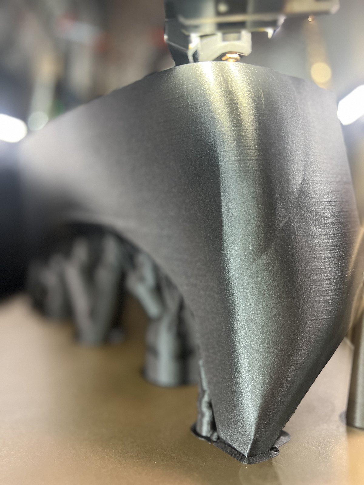
Sharp macro of a black PA12 part being printed mid-process, crisp layer texture catching the workshop light MID-PRINT · MACRO
James Crisford, 3DPE co-founder
Freddy Blake, 3DPE co-founder
SKETCH · PHOTO · PHYSICAL PART · CAD FILE

Got a CAD brief, a sketch, or a part that needs reverse-engineering? Start a project, or send us the file for a free written DfAM review first.

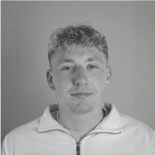
You'll get James or Freddy directly. No account managers, no form-auto-replies, no "a team member will be in touch".

Questions, answered

CAD & design — frequently asked

Yes, by default. Standing confidentiality obligations apply to every enquiry that arrives in our inbox · the moment you email us about a project, an NDA is in force without you having to ask. We're happy to counter-sign your own NDA if you prefer paper, or use our standard NDA (PDF in the footer).
We design in SolidWorks-compatible parametric workflows. We deliver STEP and IGES as standard, which open in any major CAD package (Fusion 360, Inventor, Creo, NX, Onshape, Rhino). Native editable source files on request.
Both. STEP + IGES out as standard. Editable parametric source (part + assembly + drawings) on request at project close. No clawback, no ongoing licence, no per-copy fee.
Yes. Half our enquiries arrive that way. For simple geometry a good photo with a ruler in frame is usually enough. For complex geometry we'll ask you to post the part so we can scan it (Royal Mail Special Delivery both ways, original returned tracked).
FDM holds ±0.2mm comfortably, ±0.1mm with care on a well-tuned printer. SLS and MJF hold ±0.1mm routinely, ±0.05mm on critical dimensions with first-article inspection. Tighter than ±0.05mm we'll refer out to CNC or metrology specialists.
DfAM on your existing CAD is fine · you don't have to hand the design over. We'll mark up wall-thickness issues, support strategy, orientation, infill, post-processing, and return a written review. Bundled discount if you then have us print the part.
Yes. We have a short list of UK CNC and metrology shops we trust. If we genuinely don't think 3D printing is the right process for your part, we'll tell you within 2 working days and point you to someone who is.
Yes. CAD work bundled with print is discounted to reflect the joined-up workflow · you avoid the second supplier handover and we keep the print profile on file for re-runs. Specific discount agreed at the Brief call.